
Installation
Tips & Tricks
Side Rail Installation Tutorial

Side Rail Install – Step 1
After removing the dust cover and the axis pin’s shephards crook retaining wire, remove tension from the hammer spring to facilitate axis pin removal (and to avoid hammer spring “bite” to your hand). This is best done by pulling up the two wings of the braided wire hammer spring and securing the wings behind the hammer head with a bread wrapper twist tie.
Side Rail Install – Step 2
My recommendation of how to place the AK Master Mount™ side rail: Use a small punch or long nail to follow your factory axis pins out of the receiver from right to left. This keeps your trigger and hammer assemblies in place so you don’t have to fight the springs.
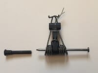
Then place the female end of my long bolts over the tip of the punch / nail and follow it back thru the receiver from left to right. Once again this keeps the hammer and trigger assemblies in place. Align the octagon head of my proprietary bolt in the corresponding cut-out in my rail and secure the bolt loosely with my short screw. Do one pin at a time.
The “Sweet Spot”
The AK Master Mount ™ side rail is held to the AK receiver wall by side compression. The underside of the two Allen head screws must compress firmly against the right outside receiver wall in order to have the adequate compression needed to keep the side rail tight against the left receiver wall.
So if you are experiencing slight movement of the side rail after installation, remove the Allen head screw from each hex pin to ensure the end of that pin is not flush with the outside receiver wall. Because the receiver walls actually flex inward during tightening of the Allen head screws, you want the shaft end of the hex head pins inset into the right receiver wall. Remember we are working with an AK, so there can be variations in receiver width.
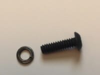
The quickest way to check if pin length is the issue for your side rail’s movement is to add a couple of washers underneath the Allen head screw before installation. Just make sure the center hole in the washer is bigger than the hex pin shaft’s diameter.
This in effect simulates a wider receiver and ensures the underside of the Allen head screw is actually compressing against the outside receiver wall and not just “bottoming out” on the shaft end of the hex pin. Once this diagnosis is confirmed, remove the washers and use a metal file to remove some metal material from the shaft end of the hex pin. Do not worry about removing too much.